Shape Builder
What it is ℹ️
Draw primitives and custom geometry directly in the viewport with live previews, snapping, and precise controls.
When to use 🧩
- Blocking out levels and paths
- Creating walls, floors, ramps, stairs, wedges, cylinders, sectors, and spheres
- Drawing smooth curves for roads, rails, pipes, and organic shapes
- Making clean, repeatable geometry with consistent dimensions
Workflow 🛠️
- Choose a shape and draw mode in the panel.
- Enable grid or surface snapping as needed.
- Click in the viewport to place points.
- You will see a preview as you set points.
- You can change settings while placing points. The preview updates accordingly.
- Building will end after placing the last point.
- You have created a shape.
Supported shapes

Shape - Block
Draw Modes
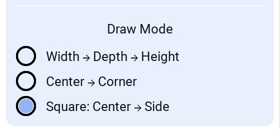
Width → Depth → Height
Center → Corner
Good when working with Grid, especially when creating many blocks and minimizing clicks.
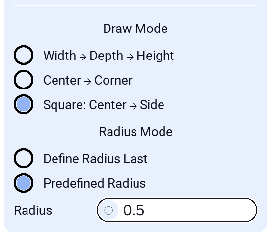
Square: Center → Side
Constrained square variant of the center-based mode. Click the center, then a side direction; width and depth are locked to be equal (square footprint). Great for fast, perfectly square floors/walls while staying aligned to the work plane and grid.
Preset Size (locked dimensions)
In Width → Depth → Height mode you can lock any of the three dimensions to a fixed value so you don't have to click to define it. This is great for repeatable footprints and for stamping parts at a constant height.

- Width / Depth / Height: Type a value (studs) to lock that dimension. The corresponding click is skipped and the part is built using the preset value.
- Dynamic (0): Leave a field empty or set it to
0to keep drawing that dimension with the mouse as usual. - Tip: Lock just Height to drop many same-height blocks in one click each; lock Width and Depth for a fixed footprint you can place repeatedly.
Shape - Plane
Create a rectangular plane aligned to the current work plane. Useful for floors, walls, and reference surfaces.
Modes
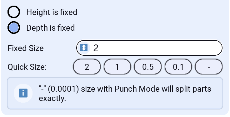
- Height is fixed: Locks height to a numeric value while you place width and depth. The fixed height is centered around the grid so adjustments feel intuitive as you move the mouse.
- Depth is fixed: Locks depth to a numeric value while you place width and height.
Settings
- Plane Mode: Choose Fixed Height or Fixed Depth
- Fixed Size: Numeric value for the fixed dimension (studs)
The Plane shape supports Punch mode to cut thin openings or surface slices out of other parts.
Set Fixed Size to "-"(0.0001) while using Punch Mode to split parts exactly along the plane (precise slicing).
Shape - Cylinder
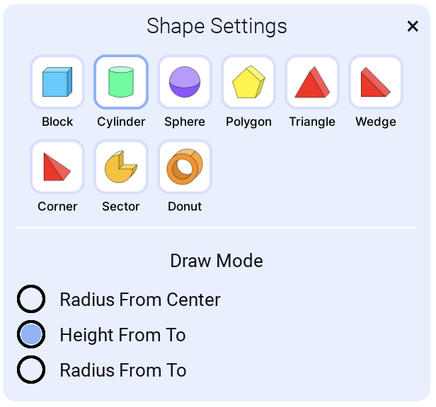
This creates a Roblox Part where the Shape property is Cylinder.
Draw Modes
You can choose from different draw modes to easily create cylinders for each scenario with accuracy.
Radius From Center
When you know where you want the center of the cylinder to be.
Height From To
When you want to create a cylinder on a surface, for example as a pipe.
Radius From To
When you want to create a cylinder so edges span from one point to another.
Shape - Sphere
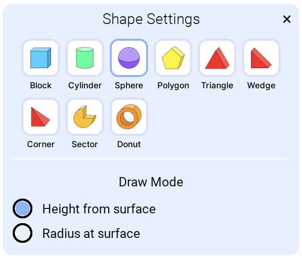
Draw Modes
You can choose from different draw modes to easily create spheres for each scenario with accuracy.
Height from surface
When you know how high you want the sphere to be in relation to other shapes in your build.
Radius at surface
When you know the width of the sphere. Especially good when working with Grid.
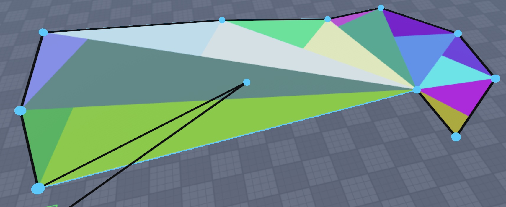
Shape - Polygon
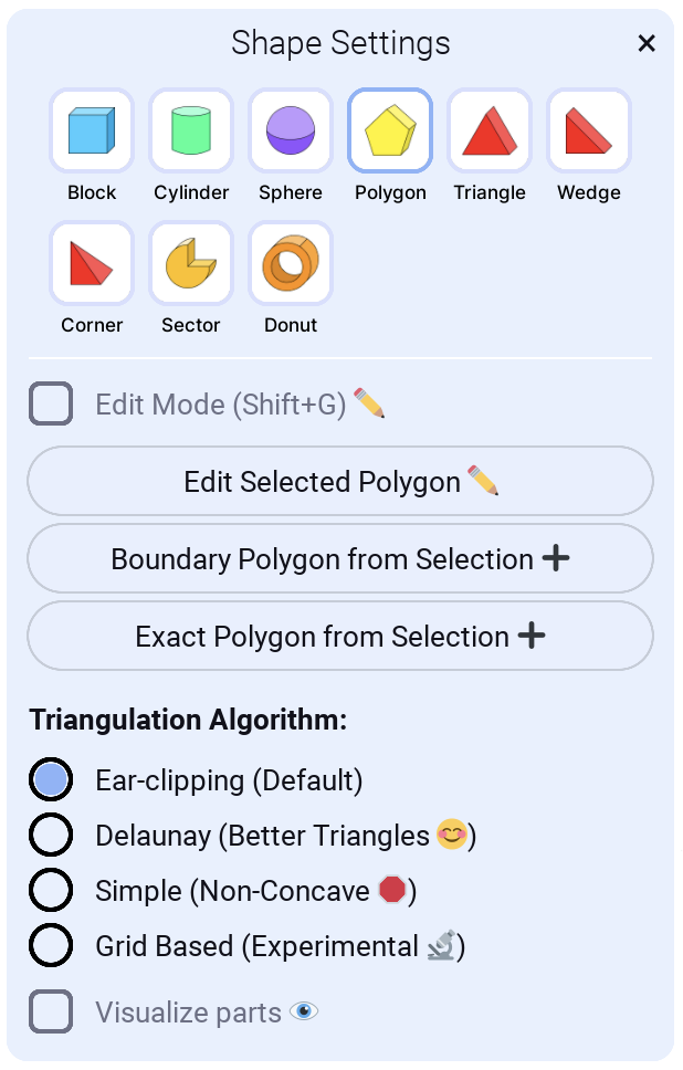
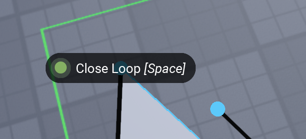
Set as many points for your polygon as you like. You can undo or go to "Edit Mode" if you misplaced your point. To finish building go near first point and click the "Close loop" button (Or press Space any time to close loop). Your last and first point will be connected perfectly. And then you can define the height. And after that you have created a polygon shape.
Triangulation Algorithm
You can set different triangulation algorithms. The default is fine in most cases. If a polygon is not drawn correctly, try changing the algorithm:
- Ear-clipping (Default)
- Delaunay (Better Triangles - does not create long and narrow wedges)
- Simple (Non‑concave — not needed in most cases; does not work with concave polygons)
- Grid Based (Experimental)
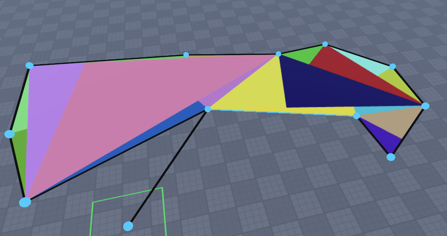
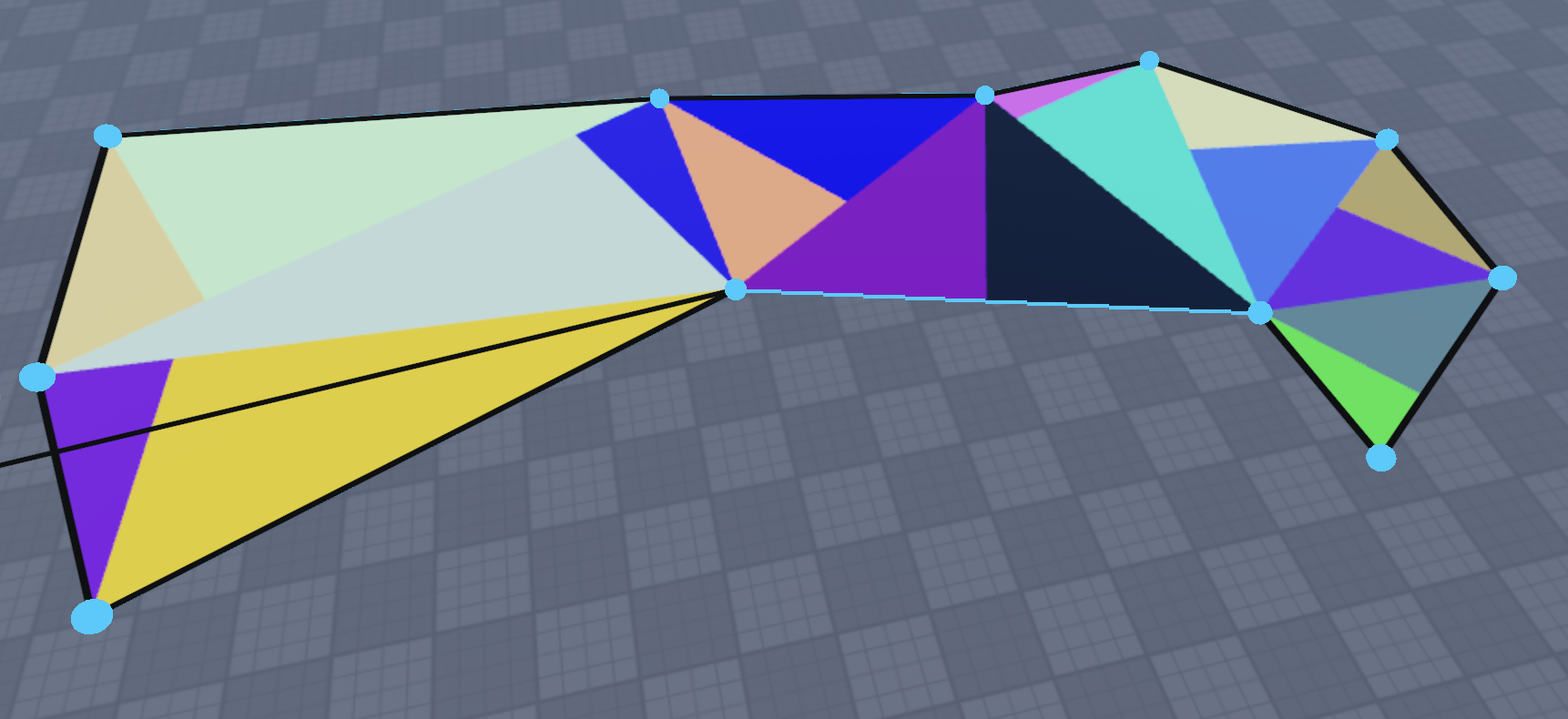
When the "Visualize part" setting is enabled, you can see the difference in wedge generation:
-
Ear-clipping
-
Delaunay
-
Simple
Demo of using Triangulation Algorithm and Visualize part settings
Edit Mode
When you enable "Edit Mode" for a polygon, you can remove, move, and add points:
-
Remove point: Click a point; when selected it turns red and you can press Backspace/Delete to remove it.
-
Add point: Click an edge to create a point, then click & drag the point. Or click & drag directly on the edge to create and move a point immediately.
-
Move point: Click & drag a point to move it; release when done.
Edit selected polygon
You can edit an already created polygon. It does not have to be created with this plugin. It can even be a plain Part.
Select all the parts that make up a polygon, or a folder/model that contains those parts as children.
Then press "Edit Selected Polygon ✏️". It regenerates all corner points including the height point and goes into Edit Mode. Then you can change height or move/remove/add points. When done, either:
- Exit "Edit Mode" by unchecking Edit Mode checkbox (or using shortcut Shift+G)
- Click "Finish Building" (or using shortcut Shift+T)
Note: Separate the UnionOperation before editing; otherwise you’ll be editing its bounding box.
Boundary polygon from selection
Good if you want to connect two shapes that are not connected. Select any number of parts, click "Boundary Polygon from Selection ➕", and a polygon with boundary points around your selection is created. Define height and you are done.
Exact polygon from selection
This functionality is a predecessor to "Edit Selected Polygon". It creates a copy of the selected polygon and lets you define the height. Of course, you can go into Edit Mode yourself. This might be removed at some point, or become an "Edit Selected Polygon" that copies instead of editing. The idea is you could do low‑poly mountains by creating a base polygon, then copying and editing the height and some points to gradually go higher.
Demo of going into edit mode while creating a polygon
Demo of Editing a Polygon from selection
Demo of creating Polygon from selection
Shape - Triangle
Shape - Wedge
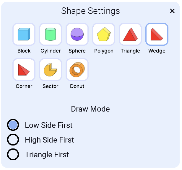
Draw Mode
Low Side First
High Side First
Use High Side First when you want to add a wedge against a part and can snap to part corners for perfect alignment.
Triangle First
If you need a wedge on its side.
Shape - Corner
Shape - Pyramid
Build a pyramid made of four CornerWedge parts that meet at a shared apex.
Draw Modes
- Width → Depth → Height
- Center → Corner
- Square: Center → Side
Shape - Platform
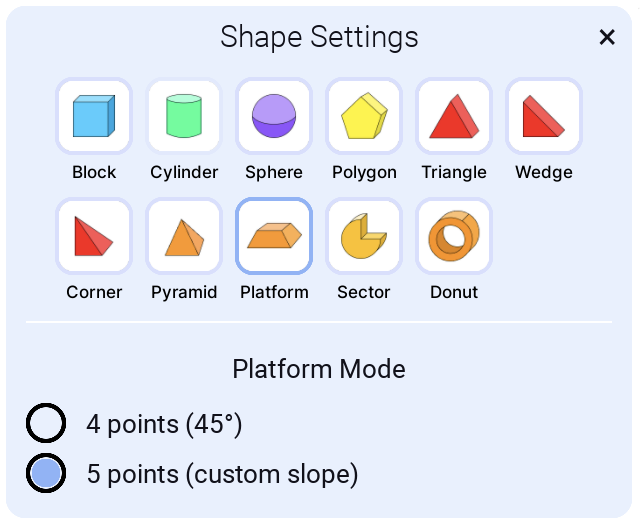
Create frustum of a pyramid, in simple terms - a platform.
4 points (45°)
Predefined slope, for quick platform
5 points (custom slope)
For last point you will defined slope, it can be inwards or outwards. So you can create upside down platform.
Shape - Pill
Create a rounded capsule-like block.
Draw Modes
- Width → Depth → Height
- Center → Corner
- Square: Center → Side
Shape - Roundbox
Create a fully rounded rectangular block (rounded edges and corners). Great for soft, polished shapes and filleted blocks.
Draw Modes
- Width → Depth → Height
- Center → Corner
- Square: Center → Side
Radius Modes
- Define Radius Last: after setting width/depth/height, place one extra point on the top face to set the inner flat size; the radius is derived from that, letting you visually dial in the corner roundness.
- Predefined Radius: type a numeric radius that is used directly (default 0.5). Radius is clamped so it never exceeds half of width/depth/height.
Works with Punch mode to cut rounded openings.
Shape - Quadbox
A performance-friendly rounded rectangle variant. Produces straight top/bottom faces with rounded vertical corners (no corner spheres or top/bottom edge cylinders), ideal when you want rounded sides at lower part counts.
Draw Modes
- Width → Depth → Height
- Center → Corner
- Square: Center → Side
Radius Modes
- Define Radius Last: after setting width/depth/height, place one extra point on the top face to set the inner flat size; the radius is derived from that, letting you visually dial in the corner roundness.
- Predefined Radius: type a numeric radius that is used directly (default 0.5). Radius is clamped so it never exceeds half of width/depth/height.
Shape - Sector
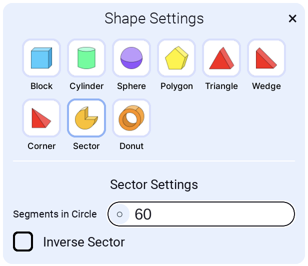
Segments in circle
This is the segment count for a full circle. For a quarter sector, it uses one quarter of the segments. For example, with 60 segments, a 90° sector uses 15. Default is 60. Here is one with 6 segments:
Inverse Sector
Change the direction of sector cutting: left vs right.
Shape - Donut
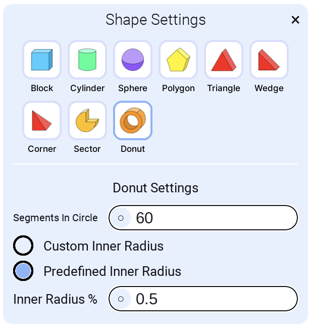
Segments in circle
This is the segment count for a full circle. For a quarter segment, it uses one quarter of the segments. For example, with 60 segments, it uses 15. Default is 60. Here is one with 6 segments:
Here is one with 3 segments and "Custom inner radius":
Custom inner radius
You define the inner radius after setting the full radius.
Predefined inner radius
You can define the percentage that the hole will be from the width. Default 0.5, so 50%.
Donut demo
Shape - Stairs
Create diagonal staircases with configurable step dimensions. Steps automatically calculate along the diagonal from the starting point to the height point, making it easy to build staircases of any angle and length. Supports both upward (positive height) and downward (negative height) stairs.
Draw Mode
Width → Depth → Height
Same draw mode as Block. Click to place:
- First point: starting corner of the stairs base
- Second point: defines the width of the stairs
- Third point: defines the depth of the stairs base
- Fourth point: defines the height where the stairs should end
The stairs will climb diagonally from the base (at the second point) to the height point (fourth point). The height can be positive (upward stairs) or negative (downward stairs).
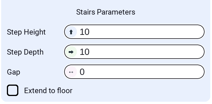
Stairs Parameters
Step Height
The vertical height of each individual step. This controls how tall each step is. Larger values create taller steps; smaller values create shorter, more gradual steps.
Step Depth
The horizontal depth of each step along the diagonal. This controls how deep each step extends. Larger values create deeper steps; smaller values create narrower steps. Steps are spaced by this value along the horizontal projection of the diagonal.
Gap
The gap between consecutive steps. Can be:
- Positive values: Creates spacing between steps
- Zero: Steps are directly adjacent with no gap
- Negative values: Steps overlap, creating a more compact staircase. With step height being small, can create overlapping hovering steps.
Extend to floor
When enabled, each step extends downward to reach the floor level. For upward stairs, the floor is at the starting point. For downward stairs, the floor is at the ending point. This creates steps that fully connect to the ground, useful for creating more complete stair structures. When disabled, steps only extend to their calculated height.
Shape - Arc
Create smooth curved arches and arcs using cubic Bezier curves. Perfect for architectural elements like doorways, windows, bridges, decorative arches, and curved structural supports.
How to use
- Select the Arc shape from the shape selector
- Click to place three points defining a rectangle (width → depth → height)
- The arc curves upward from the base rectangle using Bezier interpolation
- Adjust settings in the panel to customize the arc shape
- The arc is created automatically after placing the third point
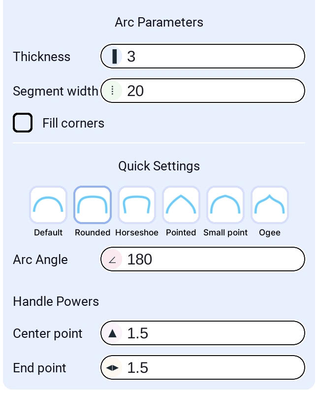
Arc Parameters
Thickness
The thickness (depth) of the arc. This controls how thick the arc appears when viewed from the side. Larger values create thicker, more substantial arcs.
Segment width
The width of each individual part along the arc curve. Smaller values create more parts and smoother curves; larger values create fewer, longer segments. This controls the resolution of the arc.
Fill corners
When enabled, fills the corners at the base of the arc with additional geometry for a smoother, more complete appearance. Useful for creating seamless transitions between the arc and its base.
Quick Settings
Choose from six preset arc styles for common use cases:
- Default: A simple, standard arc with balanced curvature
- Rounded: A thicker, more rounded arc with increased handle powers
- Horseshoe: A U-shaped arc with a deep center curve
- Pointed: An arc with a distinct upward point, creating a gothic arch style
- Small point: Similar to Pointed but with a less pronounced point
- Ogee: An S-shaped or wavy arc with elegant curves
Click any preset to instantly apply its angle and handle power settings.
Arc Angle
The angle of the arc in degrees. Controls how much of a circle the arc spans:
- 180°: A half-circle arc (default)
- 90°: A quarter-circle arc
- 360°: A full circle (though typically used for partial arcs)
Range: 0° to 360°
Handle Powers
Control the shape and curvature of the arc using Bezier handle powers:
Center point
Controls the curvature at the top (apex) of the arc. Higher values create more pronounced curves at the center:
- Lower values (0.5-1.0): Flatter, more subtle curves
- Higher values (1.5-3.0): Sharper, more dramatic curves at the top
End point
Controls the curvature at the endpoints (base) of the arc. Higher values create smoother transitions at the ends:
- Lower values (0.5-1.0): Sharper transitions at the base
- Higher values (1.5-4.0): Smoother, more gradual transitions
Adjusting handle powers allows fine-tuning the arc shape beyond the preset styles. Experiment with different combinations to achieve the exact curvature you need.
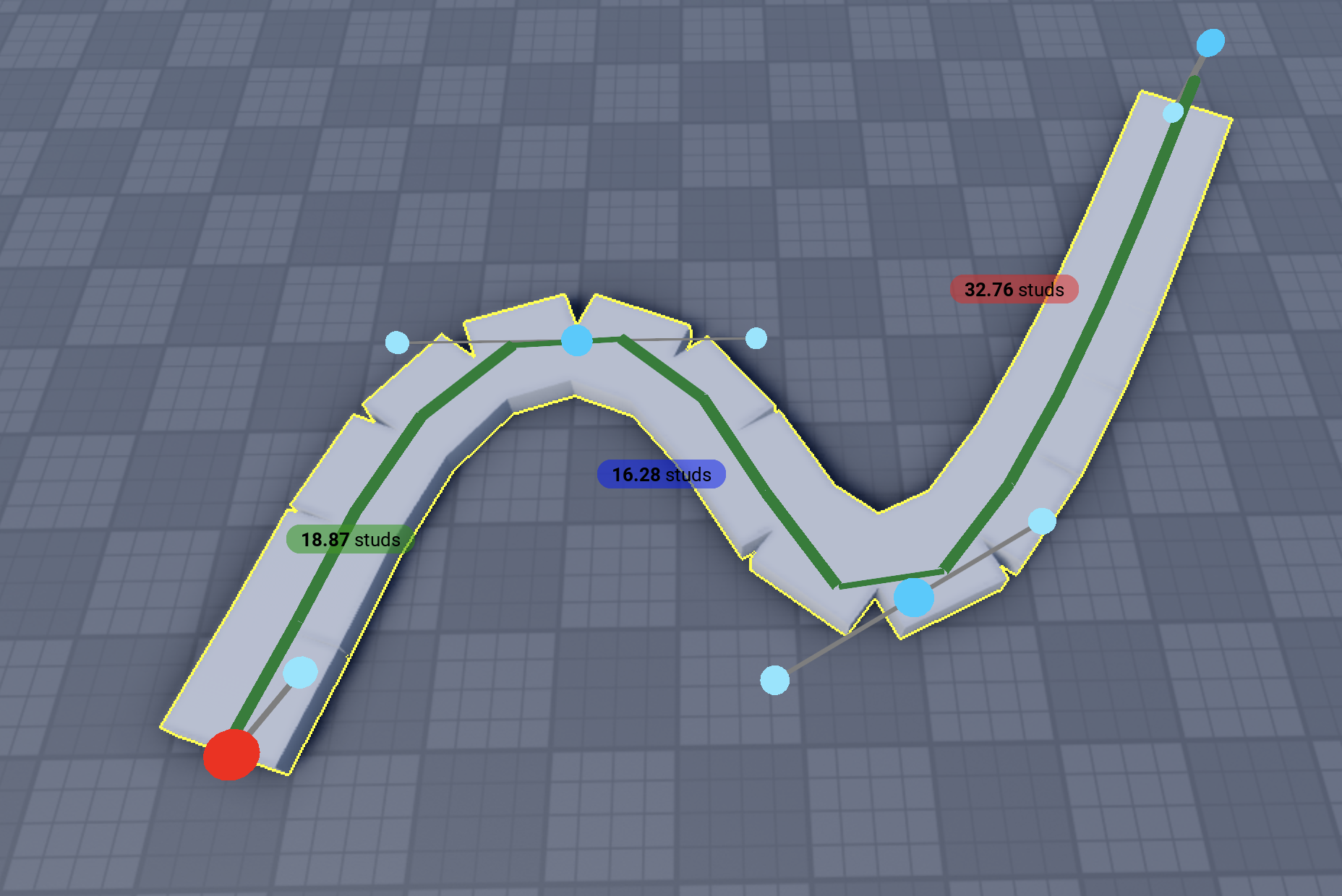
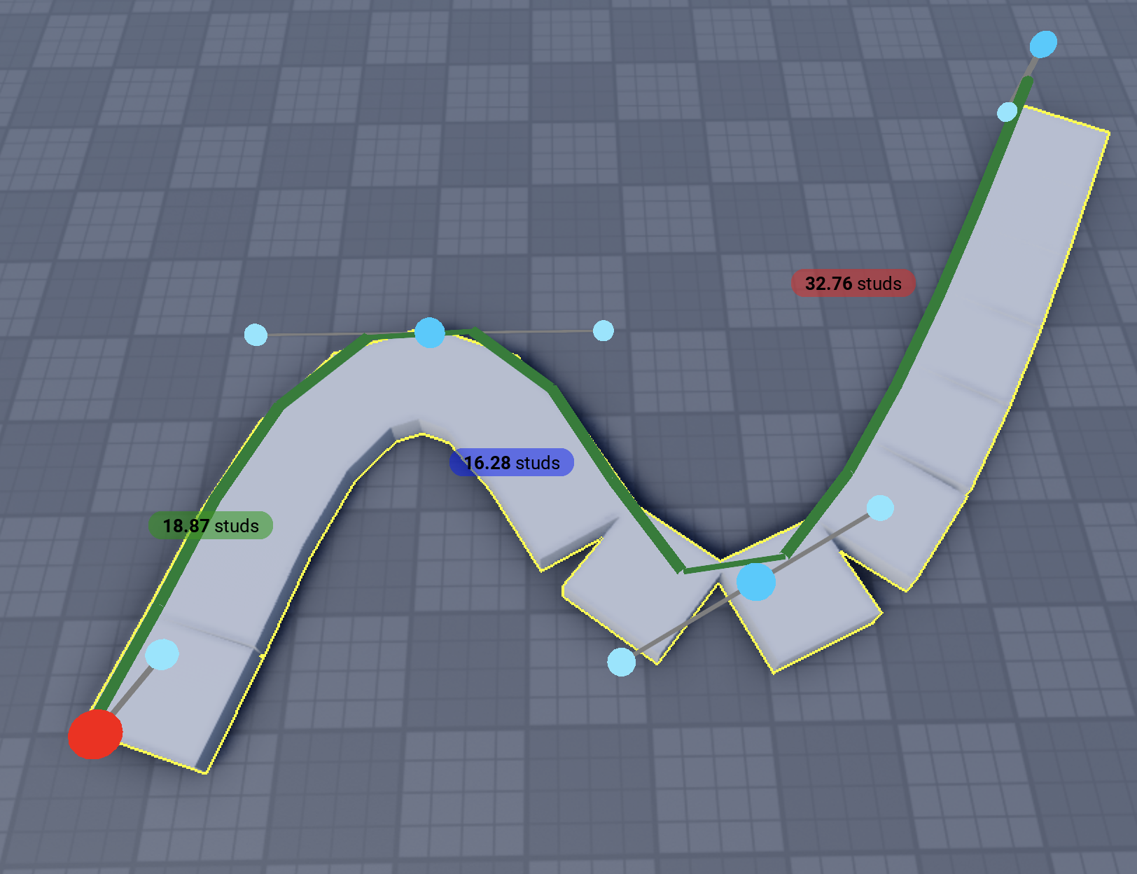
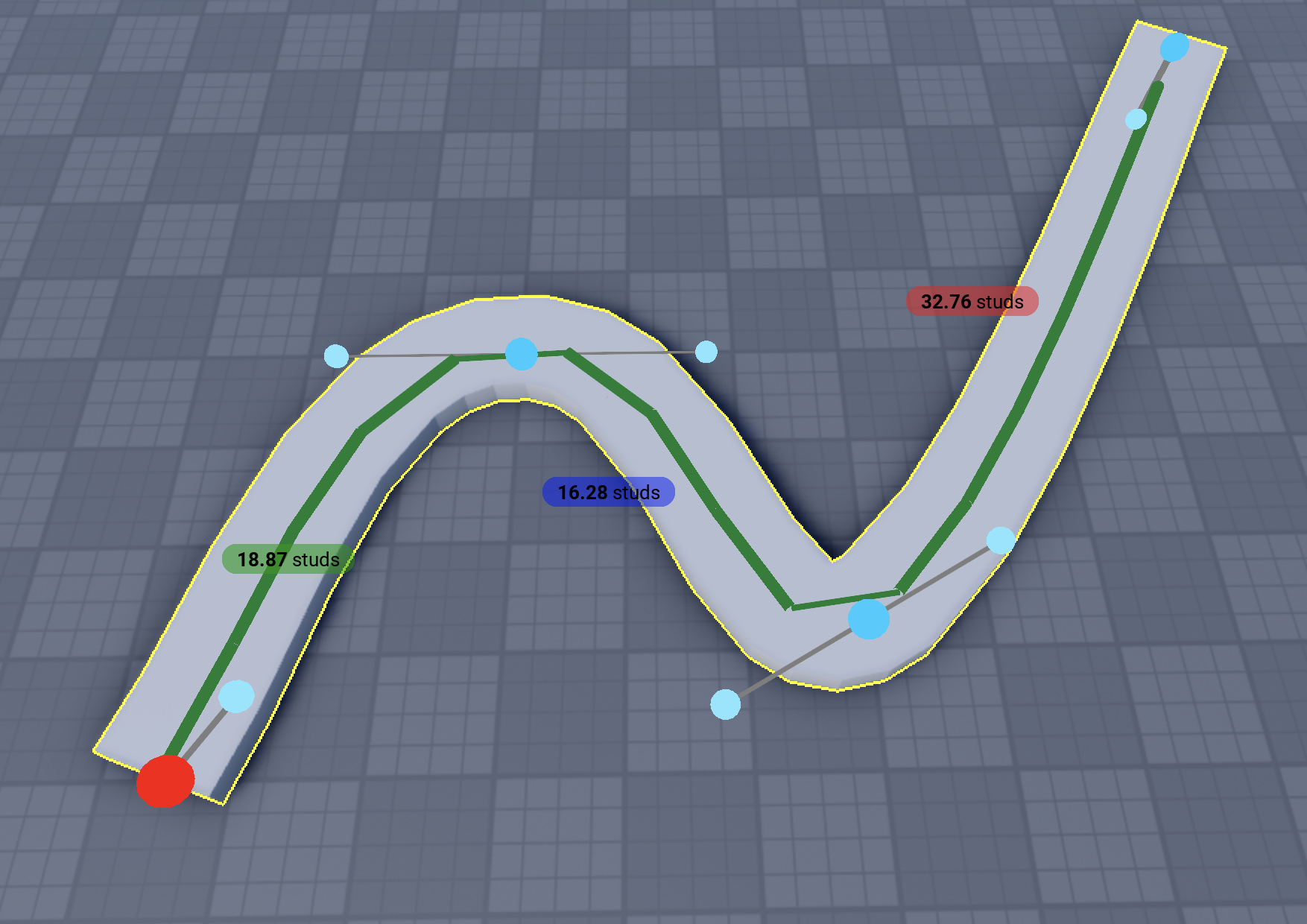
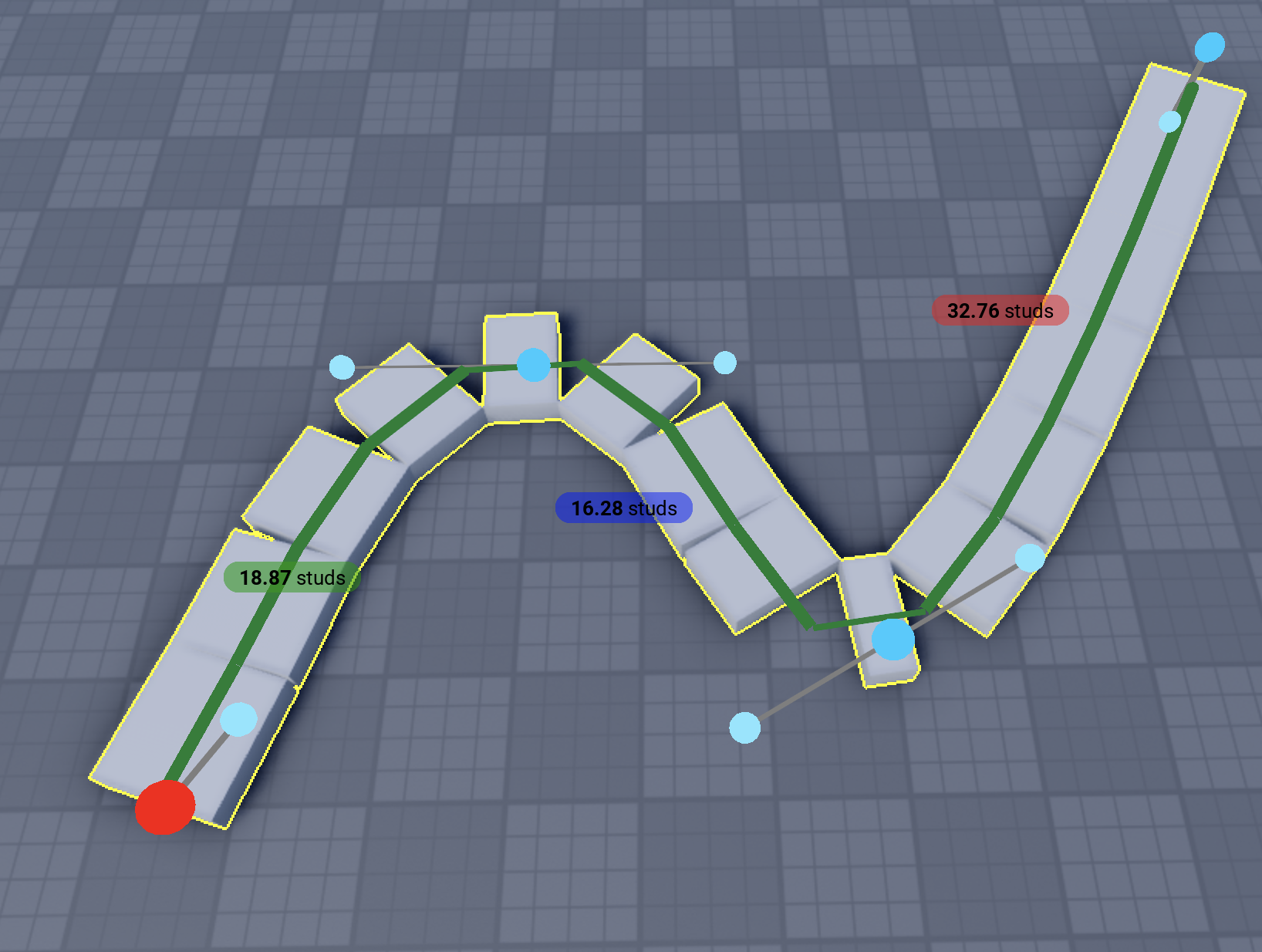
Shape - Curve (Bezier Path)
Create smooth curves by placing anchor points. The plugin generates parts along the path using smooth Bezier interpolation. Perfect for roads, pipes, rails, decorative lines, and any organic flowing geometry.
How to use
- Select the Curve shape from the shape selector
- Click to place anchor points (minimum 3 points required)
- The curve automatically smooths between points using Catmull-Rom interpolation
- Adjust settings in the panel as you place points
- Press Space or click "Finish Building" to complete
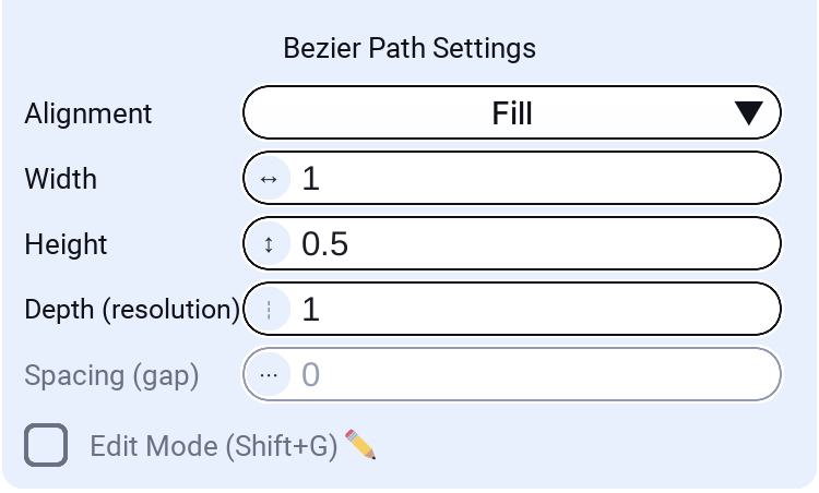
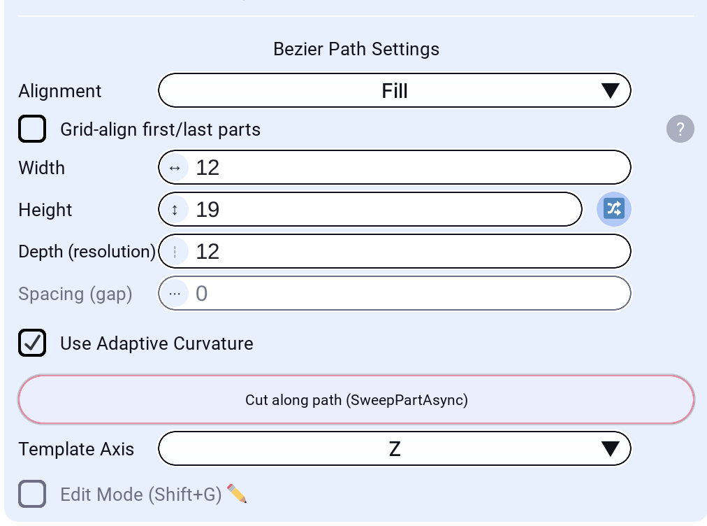
Settings
Width
The width of each generated part along the curve. This is the horizontal dimension perpendicular to the curve direction.
Height
The height (vertical thickness) of each generated part. Adjust for thicker rails, roads, or thin ribbons.
Depth (resolution)
The length of each individual part along the curve direction. Smaller values create more parts and smoother curves; larger values create fewer, longer parts.
Spacing (gap)
The gap between consecutive parts along the curve. Set to 0 for continuous geometry with no gaps. Disabled for Fill and Touch alignment modes since those modes determine spacing automatically.
Alignment Modes
Control how parts are positioned and distributed along the curve:
Center
Parts are centered along the curve path. Even spacing with gaps between parts.
Left
Parts are aligned to the left edge of the curve. Useful when building along a wall or boundary.
Right
Parts are aligned to the right edge of the curve. Mirror of Left alignment.
Fill
Parts stretch to completely fill the curve with no gaps. Uses parallel transport framing for smooth, twist-free orientation. Creates a continuous ribbon effect—perfect for roads or platforms.
Use Adaptive Curvature: When enabled, parts become smaller at curves by creating denser sampling at sharp corners. This results in smoother curves with better visual quality at bends. Enable this option if you want parts to be smaller at curves for smoother appearance.
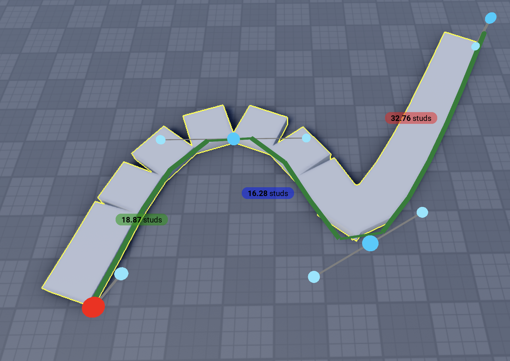
Touch
Parts are sized so adjacent parts touch exactly at their edges. Uses adaptive curvature sampling to add extra parts at sharp corners. Good for segmented paths that need to look connected.
Template Support
You can use a selected Part or Model as a template instead of simple rectangles. The template is repeated along the curve, following its orientation.
When a template is selected, the Template Axis dropdown appears:
- Z / -Z: Template's Z axis follows the curve direction
- Y / -Y: Template's Y axis follows the curve direction
- X / -X: Template's X axis follows the curve direction
This lets you orient models correctly regardless of how they were authored.
Cut along path
After placing at least two points on a Bezier path, you can subtract a swept cut from touching parts using the red Cut along path (SweepPartAsync) button at the bottom of the Bezier Path settings block.

Requirements
- Select a BasePart as the template (in Template settings). Models are not supported for this action.
- Place at least two anchor points on the curve.
- The cut uses the same path sampling as the live preview (width, height, depth, alignment, and optional grid-aligned endpoints).
What it does
- Samples the current Bezier path into sweep frames (matching how parts would be built along the curve).
- Sweeps the template part along those frames via
GeometryService.SweepPartAsync. - Subtracts the resulting hull from sliceable parts (same scope as Punch: all touching parts or only selected, per your cutter settings).
Use this to carve grooves, slots, or tunnels along a curved guide without building placeholder parts first.
SubtractAsync cut results are mesh-backed parts. Save or publish each resulting mesh to Roblox from Studio before publishing your experience. See the Tools dock warning for the full workflow.
Curve Library
The Curve Library accordion lists ready-made Bezier presets you can place in one click:
- Closed 2D: Circle, Rounded Square, Capsule, Star, Heart, Infinity ∞
- Open 2D: Half-circle, Wave
- 3D: Spring (helix)
Click Build on a preset to start placement on the active work plane. Adjust radius with your mouse, then commit like any other shape.
Save current curve: While in Bezier edit mode, use Save current curve… to store the active path under a custom name. Saved curves appear in the same list for quick reuse.
Edit Mode
Enable Edit Mode (Shift+G) to interactively adjust the curve after placing points:
- Move point: Click & drag any anchor point to reposition it
- Delete point: Select a point (turns red) then press Backspace/Delete
- Add point: Click on an edge between anchors to insert a new point
- Resize bounding box: Drag the box handles (with axis rods) to scale the whole curve
- Rotate: Use the rotation handle on the bounding box to spin the curve in the work plane
- Size labels: W, H, and D labels show the bounding box dimensions while edit mode is active
The curve updates in real-time as you edit, making it easy to refine paths. Sharp bends automatically get triangle bevels so tight corners stay visually clean.
3D Curves
The Bezier Path supports 3D curves. Place points at different heights and the curve will smoothly interpolate through all of them. The parallel transport algorithm ensures parts maintain consistent orientation without unexpected twisting.
When using Fill mode with 3D curves that change elevation, there may be small gaps between parts. Perfect gap-free surfaces in 3D would require additional wedge and corner-wedge parts, which is not currently implemented. For best results with elevation changes, use smaller Depth values to minimize visible gaps, or use Touch/Center modes with spacing.
Shape - Stamp
A stack-on-face tool: hover any part's face and click to create a new part that matches that face's footprint, extruded outward along the face normal. Perfect for quickly building up greebles, ledges, caps, and stacked details without measuring.
How to use
- Select the Stamp tool from the shape selector.
- Hover the face of an existing part — a preview appears matching the face footprint.
- Click to commit the stamped part.
Blocks stay blocks and cylinder caps stay cylinders, so the new part inherits the hovered face's shape and footprint automatically.
Settings
Height (studs)
How far the new part is extruded outward from the hovered face along its normal.
Lip (widen on all sides)
When enabled, the stamped footprint grows outward by a configurable number of studs.
- Lip (studs): How far the footprint extends beyond the original face on each side.
Dynamic lip (toward hovered edge)
When enabled, the lip overhangs only the edge or corner under the cursor instead of widening every side. Hover the center of the face to widen all sides, or hover near an edge/corner to overhang in that direction — useful for ledges and overhangs.
Demo of different shape types
Demo of building something random
Defining height demo
Demo for Wedge and Snap to Part
Shape - Voxel
A grid-cell extrusion tool: hover a cell on the work plane and drag up to stack blocks; hover the top of an existing block and drag down to carve cells away. Great for fast terrain, walls, and blocky structures aligned to the grid.
How to use
- Select the Voxel tool from the shape selector.
- Hover a grid cell — a green ghost shows how many cells you will add.
- Drag up and release to extrude blocks.
- Hover the top of a block you created — a red ghost shows removal.
- Drag down and release to remove cells from that column.
Blocks are placed relative to the current work plane and grid size, not the world axes.
Settings
Optimize resulting blocks
When enabled, adjacent same-height blocks with matching material merge into larger rectangles after each add. No CSG — only axis-aligned boxes. Wedges are excluded from merging.
Advanced building
When enabled, where you hover inside a cell picks the extruded shape:
- Cell center: a plain block (default behavior).
- Near an edge: a wedge rising at that edge.
- Near a corner: a corner wedge peaking at that corner.
Hover a wedge's top edge (or a corner wedge's peak) to resize it — drag to zero to remove it.
Related
- See Common Settings for shared options across builders
- See Keyboard Shortcuts to work faster